Unable to Detect Sending Card / Communication Failure
A
Possible Causes:
1. Poor connection of the USB cable, hardware communication failure.
2. Improper installation of the USB driver.
3. Abnormal power supply to the sending card.
4. Loss of sending card program.
Troubleshooting Steps:
1. Re-plug the USB cable.
2. Check both the USB cable and the USB interface on the computer .
3. Reinstall the debugging software (including the USB driver).
4. Replace the sending card.
Q
Error Message Prompted After Opening Debugging Software
A
Possible Causes :
1. Outdated software version.
2. Higher version of the sending card program.
Troubleshooting Steps:
1. Replace the debugging software with a newer version.
2. Downgrade the sending card FPGA version from the -D program to the -B program.
Q
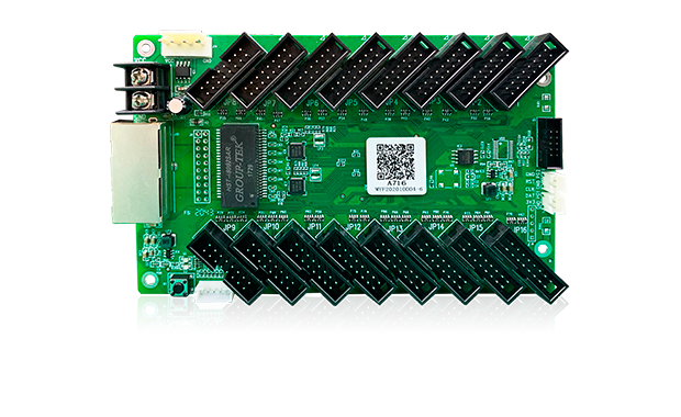
Unable to Detect the Receiving Card / No Receiving Cards Detected
A
Possible Causes:
1. Poor or disconnected network cable connection between the screen cabinets.
2. Missing or malfunctioning underlying program in the receiving card.
Troubleshooting Steps:
1. Check if the network cable is disconnected or loose and verify the power supply to the control card.
2. Replace the receiving card with a new one.
Q
Abnormal picture position/color/color discrepancies are observed within the cabinet.
A
Possible Causes:
1. Cabinet’s dual/multi-opening/customized HUB port settings do not match the cabinet design.
2. Receiver card operating mode (incorrect selection of data grouping mode).
Troubleshooting Steps:
Re-edit the cabinet program HUB port/HUB address.
Q
After a power outage and subsequent reboot, the screen may exhibit aberrant coloration or an inability to retain programmed settings.
A
Possible Causes :
1. Failure to permanently store the program settings.
2. If specific receiver cards are affected, it could indicate inherent faults within those cards themselves.
Troubleshooting Steps:
1. Re-transmit the cabinet file using the “Send Data to Device” function, followed by “Store Data to Flash.” Alternatively, utilize the display screen connection interface to transmit and permanently store the data.
2. In case of persistent issues with specific modules, repeat the process of permanent storage or consider replacing the affected receiver cards.
Q
.LED screen displaying black screen.
A
Possible Causes:
1. Partial module black screen: Possible module damage, malfunction of power chip.
2. Possible issues with the adapter board interface.
3. Possible malfunction of the receiving card, abnormal display of power/signal lights.
4. Malfunctioning sending card network port, no image output.
Troubleshooting Steps:
1. Replace (repair) the module; swap modules to isolate and repair faults.
2. Replace the adapter board or repair problematic interfaces.
3. Swap receiving cards to confirm faults; replace receiving cards.
4. Swap sending card network ports to confirm faults; replace sending cards.
Additional Possible Causes:
1. Partial module black screen may be caused by calibration activation.
2. Possible power failure or loose power terminal wire connection.
3. No signal from the front-end video source.
4. Receiving card brightness set to 0.
Further Troubleshooting:
1. Disable calibration (if calibration is activated without calibration values, the system will send data with a value of 0 to the screen, resulting in a black screen).
2. Check or replace the power supply.
3. Detect sending card signal or swap DVI cables to confirm video source status.
4. Screen control - adjust brightness values for all channels.
Additional Possible Causes:
1. Poor network cable connection.
2. If black screen occurs by network port unit, it may be due to network port communication issues.
3. If black screen occurs by cabinet unit, partial cabinets have black screens, it may be due to unstable connection between cabinets or faulty cables or network ports.
4. Possibly inappropriate version number of the receiving card’s program in the cabinet.
Further Troubleshooting:
1. Detect receiving card information and check network communication status; plug and unplug network cables.
2. Check if the receiving card in the cabinet blinks. Try replacing the receiving card. If it does not blink, it’s a cable issue; if it blinks, it’s a corresponding sending card network port issue.
3. Check if the receiving card in the black screen cabinet blinks. Determine the fault location based on blinking and non-blinking positions. Replace cabinet receiving cards or cables.
4. Check hardware/software version consistency, detect receiving cards, and upgrade to a unified program version.
Additional Possible Causes:
1. If black screen occurs only on one or two cabinets, it may be caused by receiving card faults.
2. If black screen occurs on a module basis, it may be due to poor cable connection/module or cable interface pin damage.
3. Possible power line failure.
4. Cable connected to the output port (common mistake for installation beginners).
Further Troubleshooting:
1. Swap suspected faulty receiving cards with those displaying normal operation. If anomalies persist with the receiving card’s movement, it indicates receiving card faults (without other parameter settings issues). Replace receiving cards.
2. Replace cables or modules.
3. Check or replace power lines, swap modules.
4. Check the input and output interface markings on the modules.
Q
Screen displaying pixelation.
A
Possible Causes:
1. Possible malfunction of corresponding modules.
2. Overload on the receiving card, confirming loading capacity (T6/FPGA).
3. Cable interference.
4. Electromagnetic interference (often observed with magnetically attached modules).
Troubleshooting Steps:
1. Swap modules to isolate the issue.
2. Add a receiving card.
3. Length exceeding 1.2 meters is prone to issues.
4. Separate the affected module from the metal framework.
Additional Possible Causes:
1. Cable or network line issues.
2. Network port controlling area overload.
3. Incorrect screen parameters on some receiving cards.
4. Malfunctioning sending card.
Further Troubleshooting:
1. Replace or swap cables or network lines.
2. Check the network port controlling area, resend the screen splicing program, and ensure consistency in width and height loading.
3. Verify consistency in screen parameters.
4. Replace malfunctioning sending card network ports.
Additional Possible Causes:
1. Possible mismatch in receiving card programming leading to pixelation.
2. Network port or sending card loading exceeding maximum capacity.
3. If pixelation is observed in only a few screens, it may indicate receiving card faults.
4. For screens that have undergone calibration, disabling calibration may restore normal operation, indicating potential loss of calibration coefficients.
Further Troubleshooting:
1. Inspect receiving cards, check programming, and upgrade to correct receiving card programs.
2. Calculate the loading for each network port or sending card. If exceeding 650,000 pixels or the sending card loading, consider modifying network connection schemes or using sending cards with larger load capacities. If unsuccessful, use software for pixel compression.
3. Swap suspected faulty receiving cards with those displaying normal operation. If anomalies persist with the receiving card’s movement, it indicates receiving card faults necessitating replacement.
4. Locate backup coefficients for re-transmission or disable calibration. Avoid using calibration coefficients for the entire screen.
Additional Possible Causes:
1. If issues occur within a single sending card’s range, investigate possible front-end signal delivery issues (hardware DVI port problems).
2. Pin damage leading to data group pixelation.
Further Troubleshooting:
1. Swap signal lines and outputs with other functional sending cards. If issues persist with hardware movement, it indicates hardware faults requiring replacement.
2. Replace interfaces, receiving cards, or adapter boards.
Q
Partial flickering observed on the LED screen.
A
Possible Causes:
1. Potential overuse of refresh rate parameters.
2. Elevated data clock or grayscale clock settings.
3. Damage to module or adapter board interfaces.
4. Malfunctioning receiving card.
Troubleshooting Steps:
1. Lower the refresh rate and adjust clock settings.
2. Decrease data and grayscale clock frequencies.
3. Replace (or repair) damaged modules or adapter board interfaces.
4. Swap receiving cards to isolate and replace faulty components.
Additional Possible Causes:
1. Defective receiving card programming.
2. Presence of error rates.
3. Faulty sending card operation.
4. If issues occur within a single sending card’s range, investigate possible front-end signal delivery issues.
Further Troubleshooting:
5. Install compatible program updates for receiving cards.
6. Verify error rates and inspect cable connections / soldering on adapter boards.
7. Investigate and replace malfunctioning sending card network ports.
8. Swap signal lines and outputs with other functional sending cards. If issues persist with hardware movement, it indicates a hardware fault necessitating replacement.
Additional Possible Causes:
9. Occurrence of flashing spots on specific modules of a single card.
10. Improper installation of receiving cards causing contact with steel structures.
11. Poor wiring connections.
12. Voltage instability in the power supply.
Further Troubleshooting:
9. Adjust parameter data clock phase settings.
10. Verify correct installation of receiving cards and consider adding protective materials behind them.
11. Replace malfunctioning sending card network ports.
12. Check power supply voltage output stability and replace with a new unit if necessary.
Q
Image blur and not displayed in pixel-to-pixel mode.
A
Possible Causes:
1. Incorrect resolution setting on the sending card.
2. Compression processing is applied to the screen connection program.
3. Scaling is performed on the computer’s graphics card.
4. Resolution mismatch between the sending card and the computer monitor in duplicate mode.
Troubleshooting :
1. Adjust the resolution setting on the sending card to match the input signal resolution.
2. Use a program that does not compress the signal.
3. Adjust the scaling setting on the computer’s graphics card to 100%.
4. Set the resolution on the sending card to match the monitor resolution.
Additional Possible Causes:
1. Front-end processor applied scaling.
2. Video source resolution is too low and not pixel-to-pixel.
Additional Troubleshooting Steps:
1. Adjust the processor to output in pixel-to-pixel mode.
2. Replace with a high-definition video source.
Q
Some LED display panels lag behind by a few frames.
A
Possible Causes:
1. Inconsistent firmware versions on the receiving cards.
2. Asynchronous video feed from the front-end processor to different sending cards.
3. Different hardware versions of the receiving cards.
Troubleshooting :
1. Upgrade the firmware on all receiving cards to a consistent version.
2. Seek assistance from the processor manufacturer to debug the asynchronous video feed.
3. Replace the receiving cards with consistent versions.
Q
Possible causes for not detecting the receiving card?
A
Possible Causes:
1. The Ethernet cable is too long.
2. Damage to the Ethernet port of the receiving card.
3. Possible malfunction of the Ethernet port on the sending card.
4. The software version may be too high for the receiving card hardware version.
Troubleshooting :
1. Replace the Ethernet cable with a Category 5 cable of length less than 100 meters.
2. Replace the receiving card to investigate hardware issues.
3. If swapping the cable to another port detects the receiving card, it confirms a port issue. Replace the sending card or select another port.
4. Use an older version of the software for detection.
Q
Unable to detect the receiving card.
A
Possible Causes:
1. Poorly connected Ethernet cable (or damaged/poor quality cable).
2. Receiving card lacks programming.
3. Receiving card has programming but no signal.
4. Issues with the interface port of the adapter board.
Troubleshooting :
1. Ensure the Ethernet cable is properly connected (replace with a good-quality cable if necessary).
2. Program the receiving card or replace it with a programmed one.
3. Replace the receiving card.
4. Repair or replace the interface port of the adapter board.
We use cookies to improve user experience and to analyze performance and traffic on our website. Please see our Cookie Policy for more information and you can change your settings here at any time.
Most websites use cookies. Cookies are small text files placed on devices to store data for future use by web servers. We and our third-party partners use cookies to remember your preferences and settings, assist you in logging in, and analyze the performance of our website.
Cookie Compliance
We use necessary cookies to perform important website functions. For example, it is used to maintain sessions, improve performance, route traffic between web servers, detect screen size, determine page loading time, improve user experience, and conduct audience data statistics. These cookies are essential for the operation of our website.
Analysis
We allow third parties to use analytics cookies to understand how you use our website, so that we can improve it. Third parties can also use this information for product development and improvement, and they may use these products on websites that are not operated by us. For example, they can be used to collect information about the pages you visit and the number of clicks you need to complete a task. We use some analytics cookies to optimize content display and enhance user experience.